Fuel System
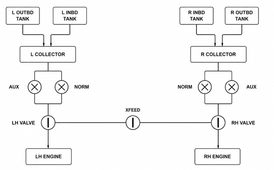
The projectmax C212 aircraft fuel system stores fuel and supplies it to the engines at the required flow and pressure. Two independent subsystems, one per wing, each collect fuel from an outboard and an inboard tank into a collector section, from which submerged booster pumps deliver fuel under pressure to the associated engine through a shutoff valve. A crossfeed line, controlled from the cockpit, permits either engine to be fed from either wing’s fuel supply.
Fuel Tanks
Each wing carries an outboard tank and a larger inboard tank, feeding by gravity into a small collector section at the root of the inboard tank. The collector houses the submerged booster pumps and represents the fuel immediately available to the engine regardless of attitude or maneuvering. Usable capacity is slightly reduced from tank capacity by a small unusable residue in each tank.
Fuel Distribution
Two electric booster pumps — NORMAL and AUXILIARY — are installed per side, each controlled by its own switch on the overhead panel. In normal operation, the NORM pump supplies fuel continuously; the AUX pump is held in reserve and is selected for takeoff, landing, or in the event of a NORM pump failure.
Fuel from the booster pumps passes through a shutoff valve before reaching the engine-driven fuel control unit. The shutoff valve is controlled electrically by the FUEL switch on the overhead panel and is also closed automatically by the EMERGENCY SHUTDOWN lever or upon fire-bottle discharge, whichever occurs first — the valve position responds to whichever of these conditions demands it, with a short, realistic transit time as it drives to the commanded position (extended further if a valve fault is present).
Fuel Crossfeed
A crossfeed valve, controlled by the FUEL FEEDING lever on the overhead panel, connects the two wing fuel supplies. Moving the lever to XFEED opens the valve and illuminates the red XFEED light, allowing either engine to draw fuel from either side. In NORMAL, the valve is closed and each side is isolated to its own engine.
Fuel Quantity Indication
Each wing subsystem has a fuel quantity gauge on the central instrument panel, with an associated three-position FUEL QTY IND selector:
- INB — displays inboard tank quantity only
- SUM — displays the total of outboard and inboard quantities
- OUT — displays outboard tank quantity only
This is functionally identical to the reference documentation’s OUT/INB/SUM arrangement, implemented here as a compact panel selector rather than a full rotary switch.
Low Fuel Level Warning
A FUEL LEVEL LEFT/RIGHT TANK caution light illuminates when the combined remaining fuel on that side falls below a preset threshold, warning the crew that the collector supply is approaching a level requiring attention. A FUEL PRESSURE LEFT/RIGHT ENGINE warning light similarly alerts the crew to a fall in delivery pressure from the booster pumps, and a FUEL SHUTOFF VALVE light indicates a valve that is not fully open or fully closed. All three conditions are also reflected in the aircraft’s master caution system.
EFB Fuel Pages
The aircraft’s EFB provides two dedicated fuel displays:
| # | Page | Description |
|---|---|---|
| 1 | Load & Balance | A fuel-loading page allowing ground crew or the pilot to set the desired fuel load by weight prior to departure, with an interactive station-loading diagram for adjusting left/right wing fuel directly. |
| 2 | Fuel System Schematic (under Simulations) | A live synoptic diagram of the full fuel system: both wing tanks and collectors with animated fill levels, both booster pumps per side (selectable directly from the diagram), the LH/RH shutoff valves and crossfeed valve (also selectable), animated flow-line indication, and live per-engine fuel-flow readouts. |