Electrical System
The projectmax C212 electrical system generates, controls, and distributes DC and AC power for aircraft systems. DC is the primary source, produced by two engine-driven starter-generators with battery backup; AC is derived from DC via inverters. On the ground, the aircraft can be powered by an external Ground Power Unit (GPU).
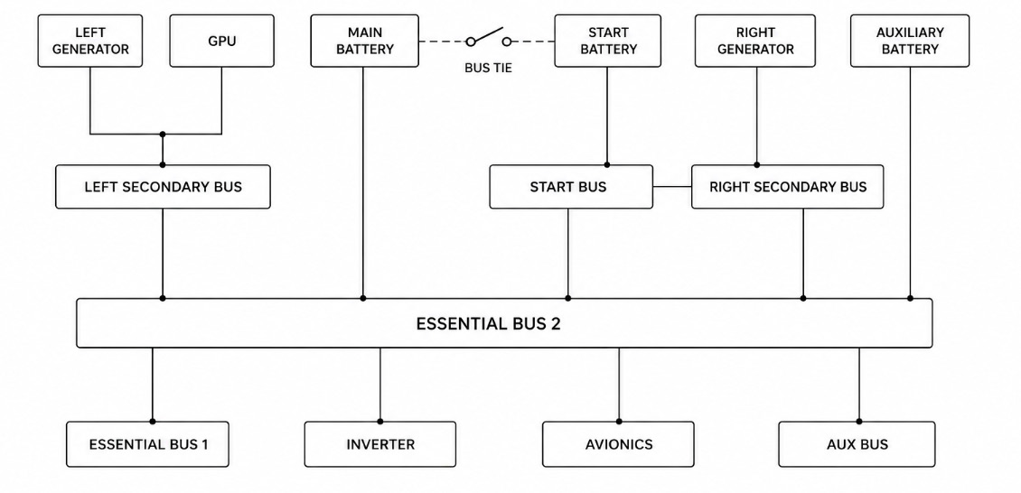
Electrical System Diagram
Direct Current (DC) Generation
Each engine drives a starter-generator (dual-purpose unit) mounted on its gearbox — used to crank the engine for start, then to generate 28 VDC (up to 300A) once running. Output is regulated by a Generator Control Unit (GCU) per side, which:
- Regulates voltage against RPM/load changes
- Prevents reverse current flow into the generator
- Trips the generator off-line on over/under-voltage or a grounding fault (test switches on the overhead panel let the crew simulate these trips)
Batteries: Three Ni-Cad batteries — two 24V/40Ah main batteries and one 24V/7Ah auxiliary battery — provide starting power and emergency backup. The two main batteries can be connected in series (48V) or parallel (24V) via a SERIES/PARALLEL switch for engine starting; series start is recommended for the first start of the day or when oil temperature is below 5°C. Each battery has a thermal probe: BAT TEMP caution at 54°C, BATTERY OVERTEMP warning at 66°C.
Ground Power: A GPU can be plugged in near the LH main gear and connected via the EXT POWER switch; batteries are automatically isolated from the bus when GPU power is selected.
DC Bus Architecture
Power is distributed via five DC buses:
| Bus | Loads |
|---|---|
| Essential Bus No. 1 | Critical loads (pitot heat, stall warning, nav/beacon/taxi lights, directional gyro) |
| Essential Bus No. 2 | Hub for most avionics (radios, autopilot, transponder, ADF/DME) |
| Primary/Auxiliary Bus | Backed by the auxiliary battery through a one-way diode (prevents backfeed to Essential Bus 2) |
| Secondary Bus | General aircraft systems, tied to Essential Bus 2 via a BUS TIED switch (NORMAL/EMERG) |
| Starting Bus | Dedicated to engine start circuits |
All DC buses are cross-tied through fuses so a single bus failure doesn’t isolate critical loads.
Alternating Current (AC) Generation
AC (115V/26V, 400Hz) is produced by three inverters — No. 1, No. 2, and a standby Auxiliary inverter. In normal operation, inverters 1 and 2 each feed their own AC bus. Each has overload protection: a fault trips the inverter offline and lights the corresponding INVERTER warning. The auxiliary inverter can be manually switched to back up either failed bus via the AUX INV/AC BUS SEL selector.
Electrical Limitations
| Item | Limitation |
|---|---|
| Starter-generator max load | 300A continuous |
| Duty cycle | 30 sec ON – 1 min OFF (repeatable once more), then 15 min OFF after a third 30-sec cycle |
| Battery operating range | −10°C to 66°C |
| Inverter load | 450 VA normal, 600 VA transient (1 min max) |